Personal design and fabrication
Six-axis Robot Arm
A six-degree-of-freedom arm built through repeated mechanical revisions, electronics experiments, and control development.
The goal
Build a six-axis robot arm that can pick up objects.
My work
Mechanical design, 3D-printed parts, electronics, and joint control.
Hardest problem
Supporting the arm’s weight and making the shoulder move predictably.
Result so far
Object pickup demonstrated; smooth position-based motion remains a limitation.
The project.
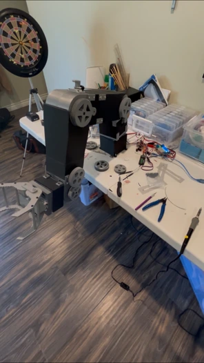
I designed and built a robot arm that can pick up objects. Starting with sketches and electronics experiments, I modeled the structure in Onshape and fabricated it through multiple rounds of 3D printing. The biggest challenges were supporting the arm's weight and making the joints move predictably.
The assembled arm has six degrees of freedom.
The working prototype can pick up objects.
Mechanical strength and predictable movement had to be developed together.
Engineering decisions
How it came together.
Build the system one component at a time
I first worked through the stepper motors, motor controllers, servos, and servo controller separately. Once the electronics worked, I modeled the base and began building upward toward the wrist. An early scale model revealed that the enclosure needed more room for the electronics, so I redesigned the base before continuing.
The shoulder became the main constraint
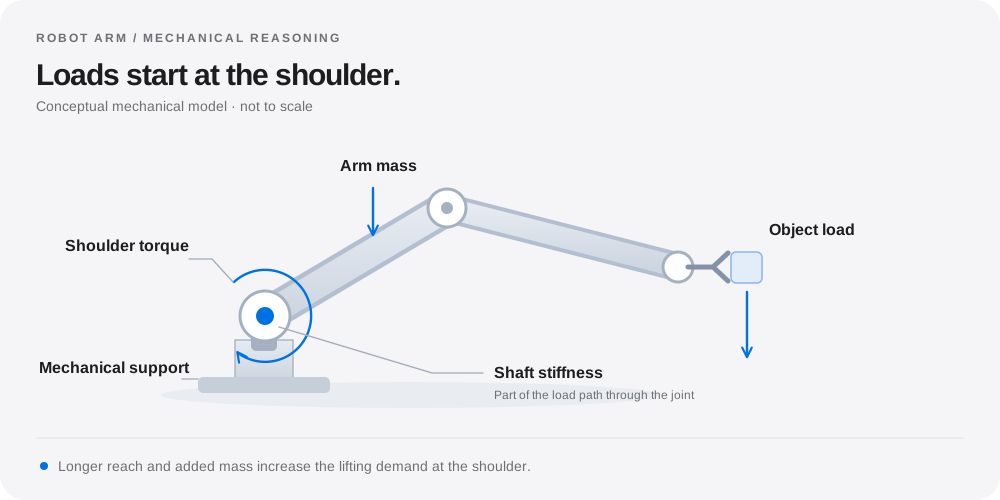
The shoulder could not lift the full arm reliably. I tried pulley assistance, installed a stronger servo, and replaced a hollow carbon rod with a stainless-steel shaft. The replacement servo introduced a new problem at the end of its travel, so I limited its range and adjusted the gear ratio to keep the movement usable.
Control that matched the hardware
I developed a trigonometric approach to calculating joint angles from a requested wrist position. It produced movement, but the motion was jittery, so I returned to adjusting the joints individually. This made the limitations clear: picking up an object and achieving smooth position-based control are separate engineering problems.
What I would redesign next
The next mechanical revision would reduce the arm's weight, improve the rotating base support, and give the joints more useful travel. I would also revisit inverse kinematics with a stronger mathematical foundation. Those changes address the load and control problems revealed by this prototype.
Explore the engineering
A small change.
A heavier demand.
Move a load farther from the shoulder and see why the arm’s lifting problem became a mechanical design challenge.
Horizontal arm · Gravity acting downward
Try the load case
τ = mass × gravity × distance
An explanatory model, not a measurement of my robot arm. It includes the payload’s static load only; arm weight, friction, and motion would add to the demand.
Development process
What changed along the way.
01 · Packaging
Give the electronics enough space
Replace the undersized early model with a larger base and revise the printed parts until the components fit and assemble correctly.
02 · Load path
Strengthen the shoulder
Combine a stronger servo, a steel shaft, and changes to travel and gearing to address lifting and abrupt movement problems.
03 · Control
Choose a usable control method
Test position-based angle calculations, identify jitter, and return to individual joint control while planning a better inverse-kinematics implementation.
Project photographs
A look at the build.
Explore the hardware, design views, and development stages.
- The robot-arm structure during development.
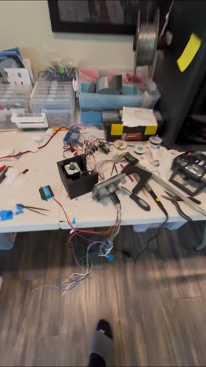
- A closer view of the build in progress.
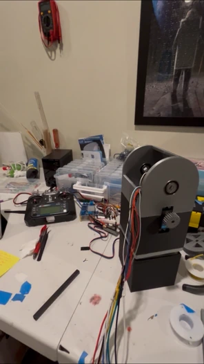
- Workshop documentation from the arm's development.
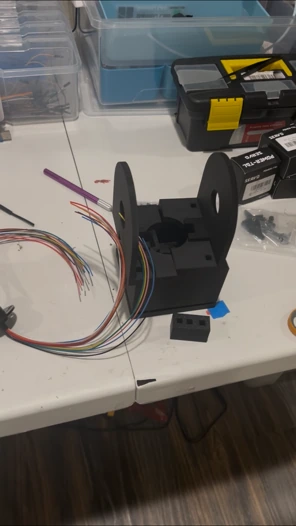
- Assembly work during development of the arm.
Skills developed