USC · Week 2
Logic Circuit Prototype
An educational circuit that mapped three simulated inputs to alert states using logic gates, flip-flops, and timer circuits.
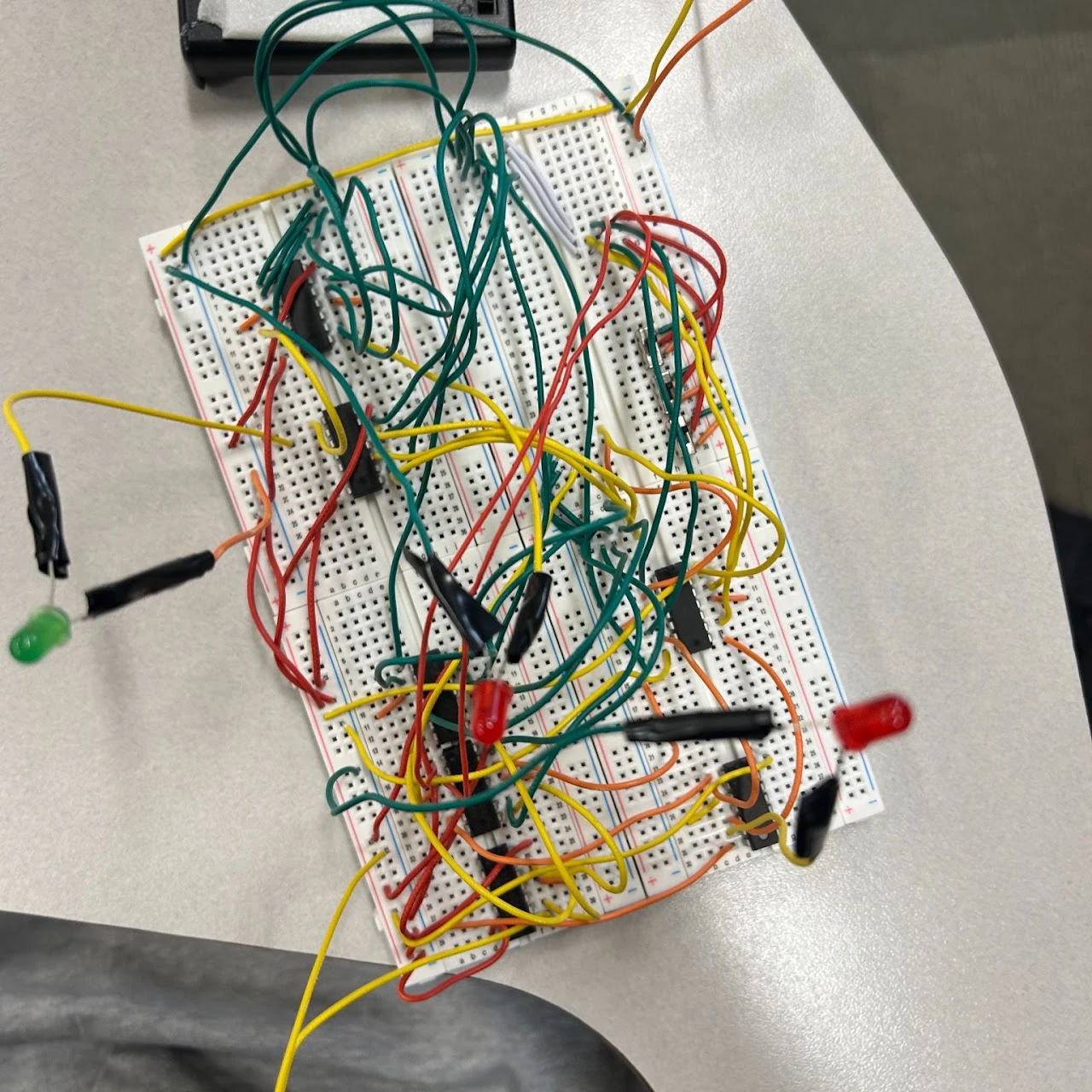
The goal
Map three simulated inputs to escalating alert states.
My work
Led the logic-circuit prototype and component troubleshooting.
Hardest problem
Timer wiring errors and an incomplete audible-alarm stage.
Result so far
Logic explored and tested; the full alarm output remained incomplete.
The project.
I led the development of a classroom logic prototype built around three simulated indicators. The planned output progressed from green to yellow to red, then an audible alarm as more inputs were active. We designed and tested the logic, but the final alarm stage remained incomplete.
A classroom exercise using a simple alert-state model.
Logic was designed and tested; the audible alarm stage still had errors.
Engineering decisions
How it came together.
Translate an idea into logic
The simulated inputs represented troponin, an ST-segment condition, and oxygen saturation. The educational design assigned green to zero active inputs, yellow to one, red to two, and an alarm to three. These were simulated signals for a circuit exercise, not a medical diagnostic system.
Build from discrete components
The prototype used 7408 AND, 7432 OR, and 7404 NOT chips, along with 74374 flip-flops and 555 timers. Working with discrete logic made the relationships between the intended behavior, the chip connections, and the physical wiring visible.
Troubleshooting changed the result
Incorrect wiring in the timer circuits caused overheating and smoke, requiring replacement components and further troubleshooting. The audible alarm still had errors at the end of the project. The final result was a partially completed prototype with a clear gap between the logic design and the complete output stage.
Development process
What changed along the way.
01 · Logic
Define the output states
Map the three simulated inputs to the intended indicator and alarm states, then develop the gate logic.
02 · Integration
Connect and troubleshoot the timers
Assemble the discrete components, investigate incorrect wiring, and replace damaged parts. The audible alarm remained incomplete.
Project photographs
A look at the build.
Explore the hardware, design views, and development stages.
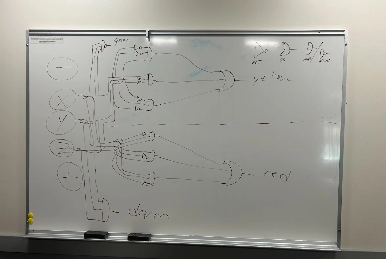
- Mapping the intended behavior to logic gates.
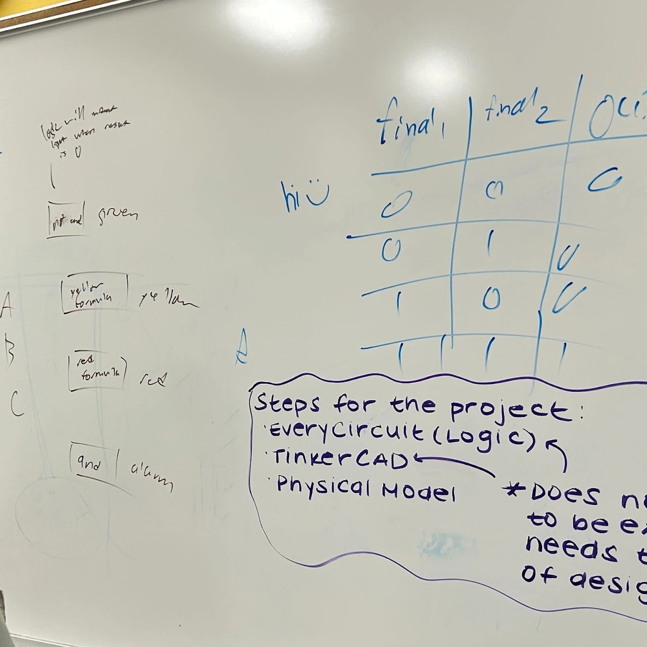
- A design sketch from the circuit-development process.
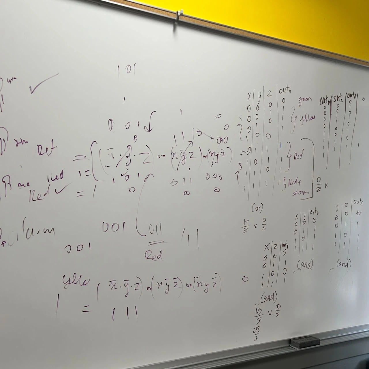
- Working through the circuit logic.
- The discrete-logic prototype during development.
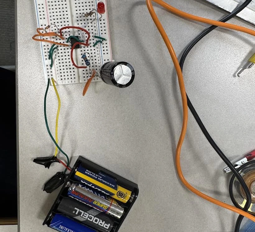
- The timer portion of the prototype.
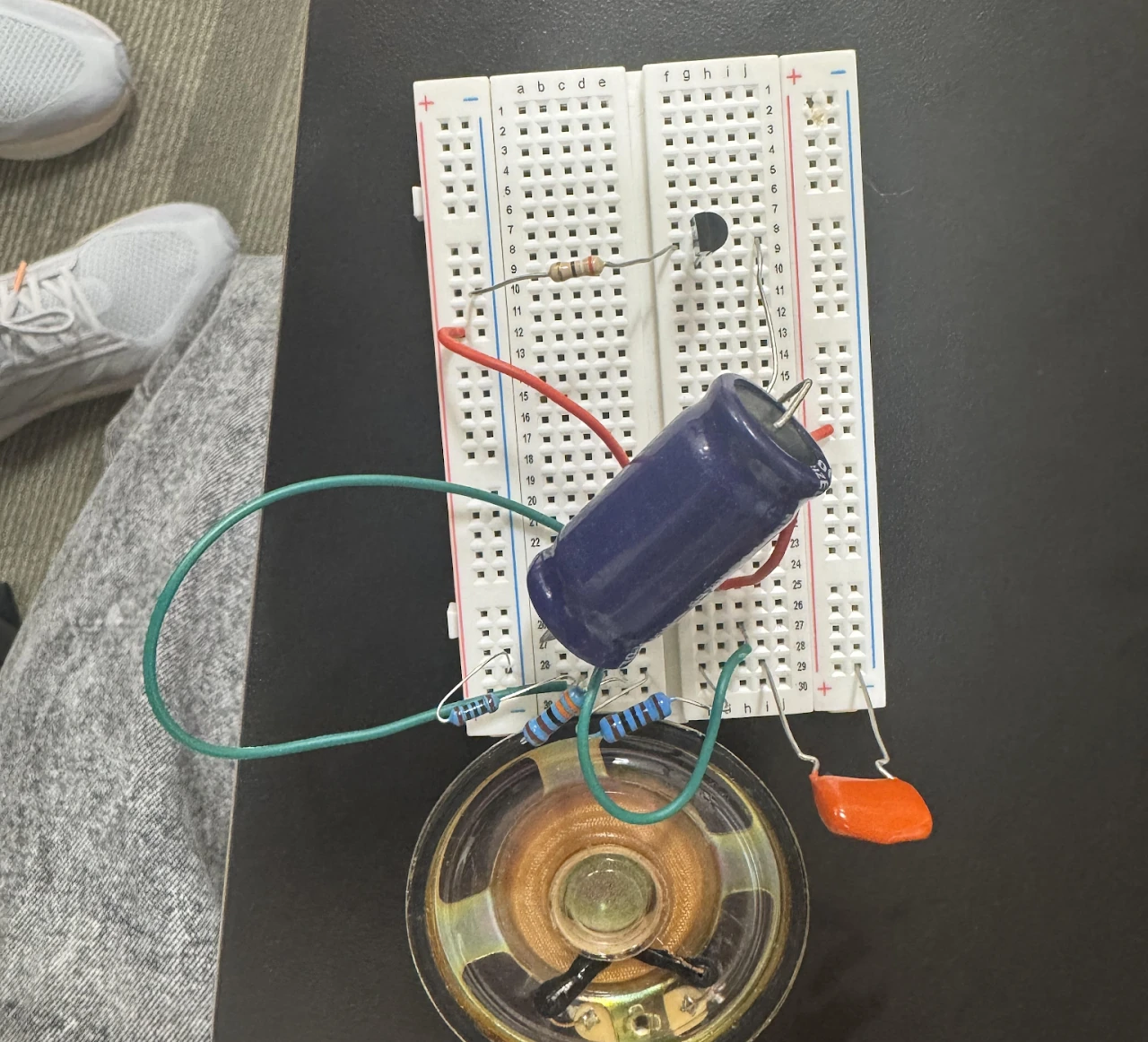
- The alarm-stage build; the final audible alarm remained incomplete.
Skills developed