Ongoing school engineering project

Cryogenic Vacuum Chamber

A cryogenic vacuum chamber for motor gearbox lubricant testing, now in final integration. I lead motor-power wiring integration and test sensor wiring while helping younger teammates install thermocouples.

WhenSophomore–junior years · 2025–Present
My roleMotor-power integration lead · Sensor wiring & testing · Student mentoring
StatusFinal integration · Preparing for motor tests
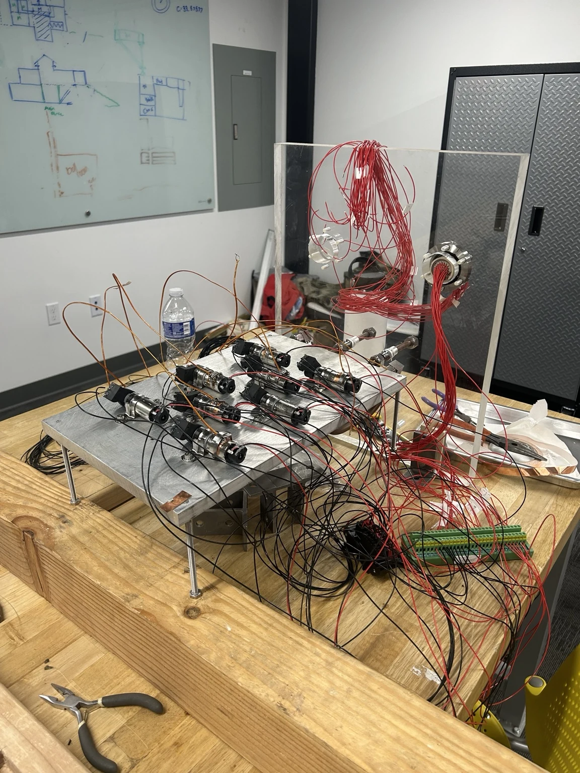
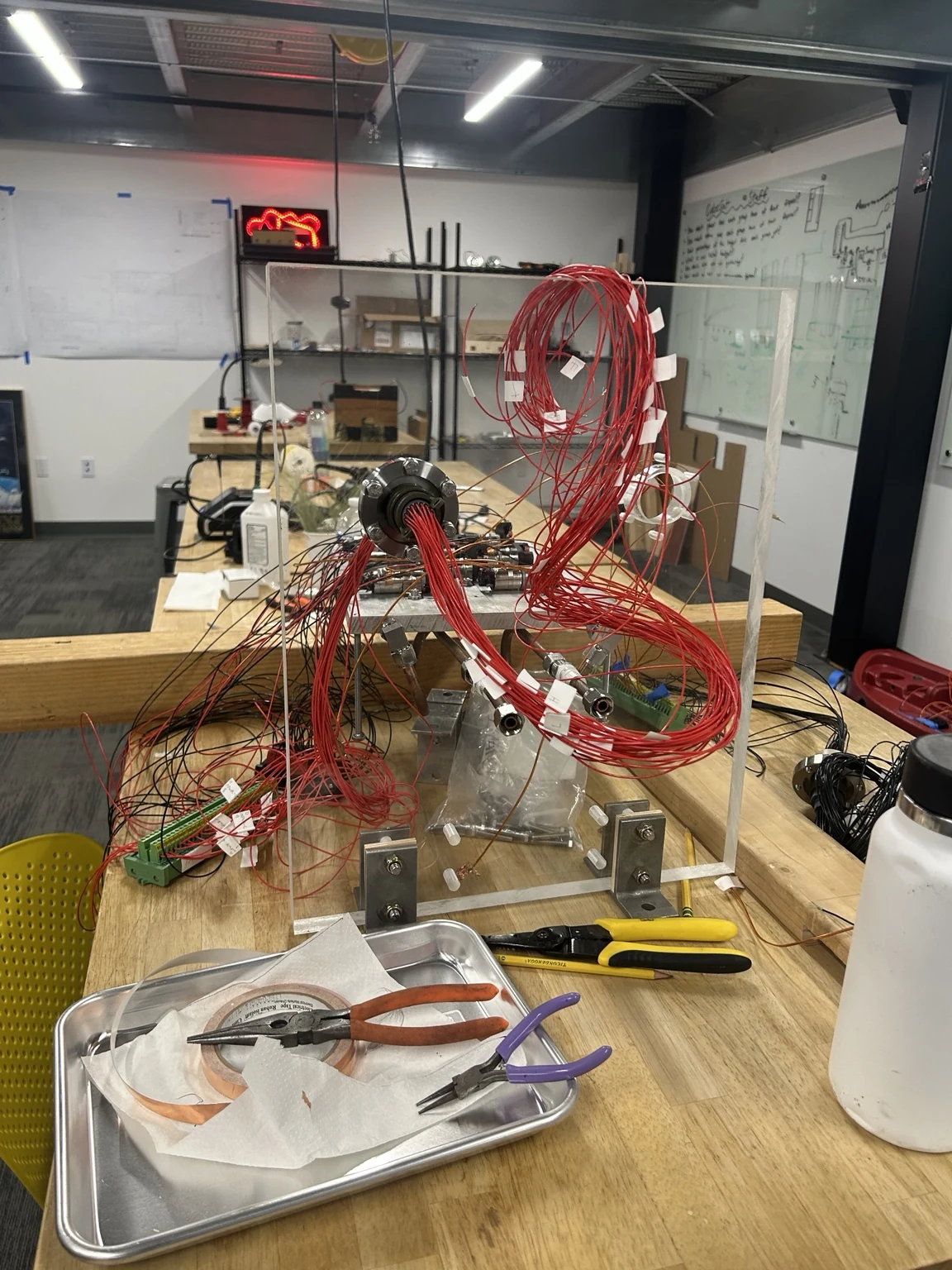
Clear chamber door made by Ruben, with the electrical feedthrough and wiring visible
Clear door fabrication and feedthrough wiring · My work

The goal

Compare motor gearbox lubricants under cryogenic vacuum conditions.

My work

Door CAD and fabrication, cryogenic plumbing, and a lead role in final motor-power and sensor-wiring integration.

Hardest problem

Integrating and testing wiring across the chamber boundary while coordinating instrumentation work.

Result so far

Final integration underway: motor-power and current-sensor wire testing, controller and logging connections, and thermocouple installation support.

The project.

Our school team is building a cryogenic vacuum chamber to compare motor gearbox lubricants, from aerospace-grade options to everyday sewing oil. The project brings together cooling, motor-test hardware, electrical connections, and instrumentation. We are now in final integration; full chamber operation and lubricant-comparison results remain ahead.

Individual work · Shared system

My work, within
the whole system.

Select a subsystem to see what I designed, integrated, or helped with—and how it fits into the team’s chamber.

Mechanical interface

Door & feedthroughs

Designed + built

My contribution

  • Created the door CAD and made the clear door across two iterations.
  • Selected feedthrough connectors and helped install them.
  • Helped finish and label 64 wires at two feedthroughs.
Clear chamber door and feedthrough wiring during development
Original development photograph

Within the wider team project

The door and electrical feedthroughs are interfaces within the larger team-built chamber. My role here was the door design, fabrication, and connection work.

Progress

Two door iterations, including a leak-path redesign and a machining-alignment correction.

2 door iterations

A bonded-layer air-leak risk prompted the second iteration, followed by a machining-alignment correction.

64 wires · 2 feedthroughs

Earlier feedthrough work included finishing and labeling 64 wires. Current integration includes testing dozens of motor-power and current-sensor connections.

Motor-power integration

Motor-power wiring, sensor-wire testing, ESP32 and logging connections, and support for sophomore thermocouple work.

Engineering decisions

How it came together.

A chamber for testing gearbox lubricants

The intended experiment compares motor gearboxes with different lubricants under cryogenic vacuum conditions. Aerospace-grade lubricants and common lubricants such as sewing oil are among the options we plan to test. The chamber brings the cooling system, motor hardware, electrical connections, and measurement electronics together.

Two door iterations, two different problems

I began by creating the door CAD for machining and also made the clear door. The first door blank consisted of two pieces glued together, with air bubbles trapped between the layers. Drilling the feedthrough bolt mounting holes could expose those voids and create a path for air to leak into the chamber, preventing it from holding a vacuum. We moved to a second door iteration. A machining error then left holes misaligned, which we corrected manually.

Build the cryogenic plumbing connections

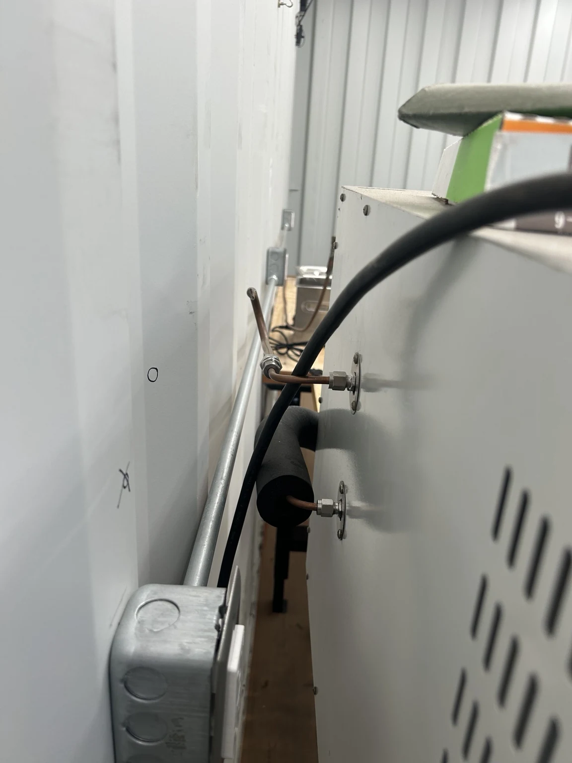
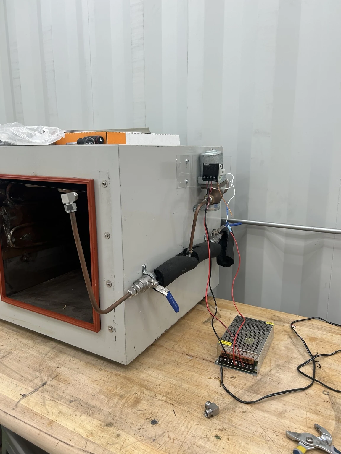
I handled the copper tubing network carrying liquid nitrogen from the dewar to the cold shroud and cold plate, then outside the chamber to vent. My work also included low-temperature insulation and tubing connectors, accounting for their tightening torque and allowing sections to be connected and disconnected. I installed two hand-operated valves to help control the nitrogen flow.

Select and install the feedthroughs

I found the appropriate feedthrough connectors and helped install them onto the door. In my junior year, I helped finish wiring and labeling the 64 wires going to two feedthroughs, connecting the door hardware with the electrical side of the project.

Wire the motor-current measurement electronics

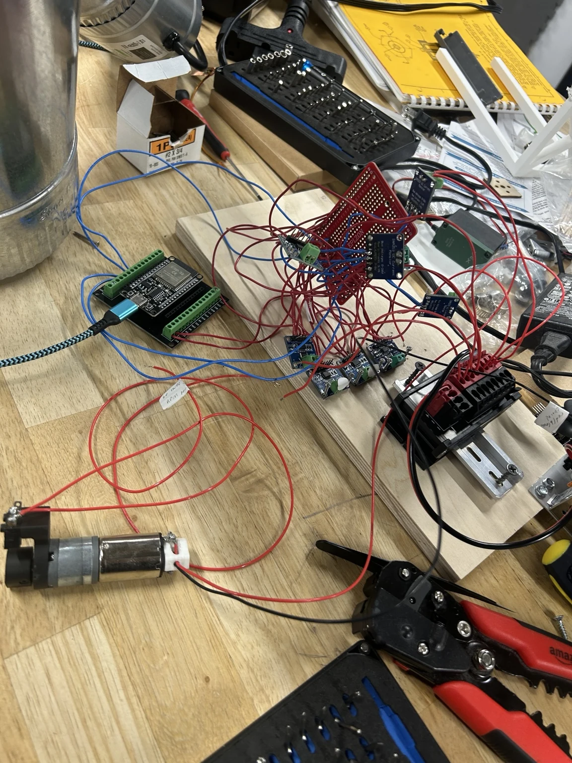
I wired four motor-current measuring boards onto a breadboard, arranging the connections so the boards could send data neatly to an ESP32. These boards are intended to support measurement of the motors’ electrical draw when the chamber becomes operational.

Lead the final electrical integration

The chamber is in its final integration steps. I have taken a lead role in integrating the motor-power wiring and testing dozens of wires between the external motor-current sensors and the motors inside the chamber. I also test wiring and attach it to the ESP32 and the thermocouple data-acquisition and SD logging hardware. Full chamber operation and comparative lubricant testing remain ahead.

Support the thermocouple and logging work

I help the sophomore team members with soldering and thermocouple installation while integrating the wiring with the controller and logging hardware. This part of the system is intended to acquire and record thermocouple data alongside the motor-test setup.
Design → Build → Revise

The drawing was
only the beginning.

Follow the problems and decisions that expanded my role from door CAD to system integration.

Bonded door layers, trapped air bubbles, and a potential leak path at a drilled bolt holeDoor blank · Section viewTwo glued piecesTrapped air bubblesDrilled bolt holePotential air-leak path into the chamberExplanatory illustration · Not a fabrication drawing

Build history / 01

A potential leak between layers

The first door blank was two pieces glued together with trapped air bubbles. Drilling the feedthrough bolt holes could expose those voids, creating an air-leak path into the vacuum chamber. We moved to a second iteration.

What it changed

The bonded layers and drilled interfaces had to avoid connected voids that could compromise the vacuum.

Project photographs

A look at the build.

Explore the hardware, design views, and development stages.

Currently in development

The next milestone.

Complete electrical and instrumentation integration before chamber and lubricant-comparison tests.

Evidence to look forVerified wiring and working thermocouple data acquisition and logging, followed by documented chamber conditions and motor measurements.

Skills developed

CADDoor fabricationDesign iterationMachining correctionCryogenic plumbingFeedthrough selectionElectrical wiring & labelingCurrent-measurement electronicsESP32 integrationTeam coordinationLow-temperature insulationTubing connectorsManual valve installationMotor-power integrationWire testingThermocouple instrumentationData loggingStudent mentoring

Project demonstration

Original project recordingOpen original video ↗